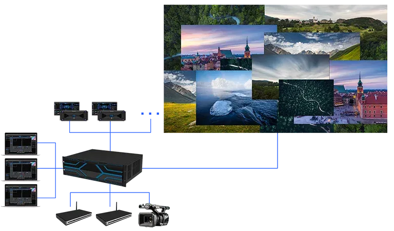
An ultra-wide source may contain far more horizontal pixels than one conventional output can carry, even when its total height is modest. The image must be partitioned into regions that fit supported output modes, then delivered so the LED wall reconstructs the original canvas without scaling errors or gaps.
A video splicing processor performs this job by acquiring the source, defining crops or windows, mapping them to outputs, and preserving the intended timing and color path across the complete display.
Turn the Source Raster into Exact Output Regions
Geometry comes before port allocation. The video splicing processor needs the source width and height, the native LED canvas, and the maximum raster of each output route. The source can then be divided into vertical or horizontal regions whose coordinates cover every pixel once. Overlap creates duplicated content; a gap discards content; unplanned scaling changes the relationship among regions.
Equal-width splits are convenient but not mandatory. Cabinet topology, processor limits, and downstream LED controllers may favor regions with different dimensions. Each crop should have a source rectangle, an output mode, and a destination on the wall drawing. That map becomes the reference for configuration and later maintenance.
Preserve Bandwidth, Sampling, and Aspect Ratio
Splitting does not reduce the bandwidth required to acquire the original canvas. A video splicing processor must accept the source at its native timing and color format before it creates output regions. If the input path reduces frame rate, chroma sampling, or resolution, no later arrangement of outputs can restore the lost information.
Kystar SEn and SHn modular platforms support end-to-end 8K processing with full RGB 4:4:4 sampling and DP 1.4 input up to 8K x 4K@30Hz. These values apply to defined interfaces and card configurations. The source device, cable path, input card, processing mode, output cards, and downstream equipment must all carry the approved format.
Source timing should remain stable throughout commissioning. A workstation that changes its desktop arrangement or output mode after restart can invalidate the crop coordinates stored in the processor.
EDID management, a fixed graphics configuration, and a documented startup sequence reduce that uncertainty. The team should also retain a full-canvas test file at the exact native raster so the system can be checked without depending on the availability of the final playback application.
Assign Windows and Outputs Without Hidden Scaling
The video splicing processor may express each region as a window or as a routed crop from a larger source canvas. Flexible placement, roaming, and scaling are valuable when content must be repositioned, but a pixel-accurate ultra-wide split should avoid unnecessary resizing. Operators should confirm the width, height, and origin of every window rather than aligning them only by eye.
Multi-layer layouts add another resource dimension. A background canvas, live windows, OSD elements, and alternate sources can consume input, layer, and output capacity differently. The acceptance scene should include the maximum concurrent layout, not merely the single background source used to establish the split.
Choose Output Architecture for the Downstream Chain
The required destination determines which video splicing processor family and cards are appropriate. Kystar SEn focuses on professional video processing and can scale to as many as 32 4K@60Hz outputs or 128 2K routes, depending on chassis and configuration. Its pure-hardware FPGA architecture supports a broad card set that can include DP, HDMI, SDI, DVI, IP, HDBaseT, CVBS, and VGA.
For projects that send directly to the LED network, the SHn architecture combines switching and splicing with LED control and reaches as many as 224 Ethernet outputs and about 147.2 million pixels. That architecture can reduce separate downstream stages when direct LED network output is required. The capacities describe different output units, so video routes and Ethernet-port pixel loads should not be compared as if they were interchangeable.
Chassis capacity is also conditional on card placement and the number of simultaneous resources in use. The proposed bill of materials should list the exact input and output cards, slot positions, active source formats, windows, and routed destinations.
This makes the quoted scale auditable and prevents a maximum family-level figure from being applied to a smaller chassis or an incompatible card combination. Spare slots can then be evaluated as genuine expansion paths rather than assumed capacity.
Commission the Reconstructed Canvas at Its Seams
Test patterns make mapping errors visible. The video splicing processor should be checked with grids, numbered regions, one-pixel lines, moving diagonals, color ramps, and content that crosses every output boundary. Static geometry reveals gaps and overlaps; motion reveals timing differences; fine patterns reveal unintended scaling or sampling changes.
Edge labels and moving diagonal lines make reversed regions, one-pixel gaps, duplicated columns, and timing discontinuities visible before normal program material hides them. Browser-based control and centralized Kapollo management can support configuration and monitoring across the system.
Access control and saved projects should preserve the approved map, while a commissioning record stores card positions, input and output modes, window coordinates, destinations, and firmware or project versions. An ultra-wide canvas is successfully spliced when each output owns a precise region and all regions return to one coherent picture on the LED wall.
The processing platform must preserve source quality, respect card and chassis limits, and keep the configured geometry recoverable after restart or maintenance. A moving, pixel-accurate seam test at the native source and output timing provides the decisive validation, rather than connector count alone.